
This article presents selected examples of antenna testing solutions implemented using Ceyear test and measurement equipment. The cases demonstrate how Ceyear products can be integrated into complete antenna measurement systems to address demanding testing requirements across a wide range of frequencies and applications.
The presented solutions cover various antenna testing methods, including near-field and far-field measurements, phased-array antenna testing and calibration, on-wafer antenna characterization, millimeter-wave and terahertz measurements, as well as RCS testing.
These application cases illustrate the capabilities of Ceyear instrumentation in real-world test environments and provide practical examples of how Ceyear-based solutions can support antenna development, characterization, calibration, verification, and production testing.
Medium-to-Large Near-Field Antenna Test System
Medium-to-Large Near-Field Antenna Test System Figure 1 shows the dual-Y-axis near-field phased array antenna test system developed by our company for a certain aerospace research institute, which can meet the testing requirements for larger-aperture antennas and offers good test accuracy.

Figure 1 Photo of the Dual-Y-Axis Near-Field Phased Array Antenna Test System
Technical specifications achieved by the system:
- Frequency range: 0.8–40 GHz
- Dual-Y-axis scanner scan range: 12 m × 5 m
- Scanner axes: 7 axes (X, Y1, Y2, Z1, Z2, P1, P2)
- Planarity: 0.1 mm (rms)
- -30 dB sidelobe measurement accuracy: ±1.5 dB
Near-Field/Far-Field Antenna Test System
Figure 2 shows a near-field/far-field antenna test system, mainly featuring planar near-field and far-field testing functions, with operating-frequency coverage of 18 GHz–170 GHz. The chamber dimensions are 13 m × 6 m × 4 m, the scanner scan range is 3 m × 2.5 m, and the maximum far-field test distance is 9 m. The above systems are able to support scientific research, teaching, and external antenna-testing services in the antenna field.
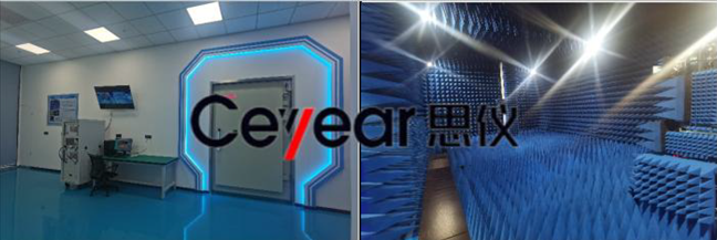
Figure 2 18 GHz–170 GHz Near-Field/Far-Field Antenna Test System
Rectangular-Range Test Platform System
Figure 3 shows the rectangular-range test platform system developed by our company for a university. The high-performance rectangular-range test platform can rapidly complete near-field/far-field amplitude-and-phase data scanning and plot multi-dimensional radiation patterns, helping to improve the overall test capability of the microwave chamber.
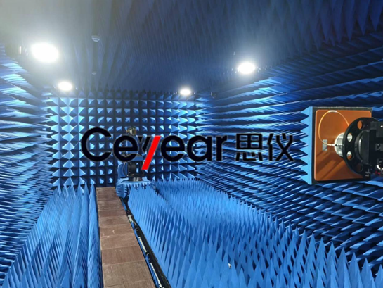
Figure 3 Rectangular-Range Test Platform
Main system specifications:
Frequency range: 1–75 GHz
Gain uncertainty: <±0.35 dB
Sidelobe test accuracy: <0.5 dB@-20dB, <1.0 dB@-30dB
Maximum test-article size: 1 m × 1 m
Chamber dimensions: 10 m × 5 m × 3.55 m
Chamber shielding effectiveness: <90 dB
Chamber quiet-zone reflectivity: <-35 dB@1GHz–8GHz, <-40 dB@8GHz–75GHz
Near-Field/Far-Field Antenna Test System
Figure 4 shows a near-field/far-field antenna test system built by our company for a client company.
The system features high measurement accuracy, strong capability for measuring large-aperture/high-gain antennas, and low site requirements. In particular, a single measurement yields holographic information on the antenna's field distribution, which for antenna designers saves both time and effort, greatly improving efficiency and shortening development cycles. It provides a fast, accurate means for the development of new antennas and has great potential for extension into other fields.

Figure 4 Near-Field/Far-Field Antenna Test System
Main system specifications:
- Frequency range: 3–40 GHz
- Gain uncertainty: <±0.25 dB, repeatability ±0.05 dB (3GHz–40GHz); <±0.6 dB, repeatability ±0.15 dB (40GHz–90GHz)
- Sidelobe test accuracy: <±1 dB@-20dB sidelobe, <±2 dB@-30dB sidelobe, <±2.5 dB@-40dB, sidelobe (3GHz–40GHz); <±1.5 dB@-20dB sidelobe, <±2.5 dB@-30dB sidelobe, <±3.5 dB@-40dB, sidelobe (40GHz–90GHz)
- Beam-scanning test accuracy: beamwidth <10°, pointing range <45°, beam-scan pointing error: ±0.2°; beamwidth <10°, pointing range 45°–60°, beam-scan pointing error: ±0.5°
- Beamwidth test accuracy: <5% of beamwidth @BW>2°, <0.05°@BW<2°
- Cross-polarization test accuracy: <±1dB@-20dB, <±2dB@-30dB, <±2.5dB@-40dB, (3GHz–40GHz); <±1.5dB@-20dB, <±2.5dB@-30dB, <±3.5dB@-40dB (40GHz–90GHz)
Array Antenna Amplitude/Phase Consistency Test System
Figure 5 shows a schematic diagram of the array-antenna amplitude/phase consistency test system provided by our company; Figure 6 shows the system's test-software interface. This system employs a near-field-extrapolation-based method for array-antenna channel-consistency testing. Using full-beam near-field scanning, it extrapolates the far-field distribution and automatically performs intelligent normalization across multiple channels, making it easy to compare the amplitude/phase consistency between channels — providing a fast, accurate means for near-field amplitude/phase
consistency calibration of array antennas.
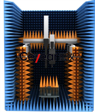
Figure 5 Schematic Diagram of the Array Antenna Amplitude/Phase Consistency Test System
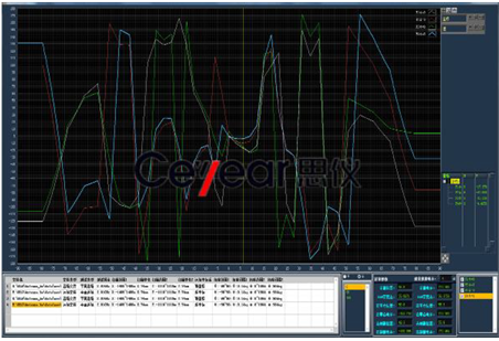
Figure 6 Array Antenna Amplitude/Phase Consistency Test Software Interface
Figure 7 shows the phased-array-antenna calibration and near-field test chamber system provided for a research institute. It adopts a compact chamber structure and planar near-field test technology, enabling automatic calibration of phased array antennas. Based on the scanned amplitude/phase data, it can output the corresponding amplitude/phase compensation data, directly usable for array-face calibration of the antenna under test. Based on the scanned amplitude/phase data, the system can obtain the array antenna's aperture-field distribution, far-field 3D radiation patterns, E-plane/H-plane 2D radiation patterns, and other required test data.

Figure 7 Phased-Array Calibration and Near-Field Test Chamber System
Figure 8 shows the array-antenna test chamber system provided for a defense-industry manufacturing plant. Operating frequency 75–110 GHz, capable of supporting the testing of antennas up to 300 mm in size. It primarily performs array-antenna pattern testing using the planar near-field method.
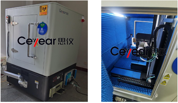
Figure 8 Array Antenna Test Chamber
Electromagnetic Characteristics Test Platform System
Figure 9 shows the electromagnetic characteristics test platform system built by our unit for a university. The chamber dimensions (length × width × height) are 10 m × 7 m × 7 m, providing far-field antenna testing capability from 0.5 GHz to 110 GHz.

Figure 9 Electromagnetic Characteristics Test Platform
Main system technical specifications:
- Frequency range: 0.5–110 GHz
- Capable of analyzing antenna pattern parameters: beamwidth, main-lobe position and level, sidelobe position and level, beam pointing, circular-polarization axial ratio, etc.
- Maximum port output power: +5 dBm
- Gain measurement error: ±0.35 dB
Radiated-Field Characteristics Diagnostic System
Figure 10 shows the radiated-field characteristics diagnostic system built by our unit for a university. The system features high measurement accuracy, strong capability for measuring large-aperture/high-gain antennas, and flexible site deployment, helping universities carry out efficient, precise testing and in-depth analysis in scientific-research and teaching scenarios such as antenna-performance research and new-antenna development.

Figure 10 Electromagnetic Characteristics Test Platform
Main system technical specifications:
Frequency range: 1–110 GHz
Effective scan travel: 3 m × 4 m × 0.25 m
Gain measurement error: <±0.35 dB
Microwave chamber dimensions: 7.0 m × 5.0 m × 7.0 m
Shielding effectiveness: >100 dB@1–18GHz, >80 dB@40GHz
Near-Field/Far-Field Antenna Test System and On-Wafer Antenna Test System
Figure 11 shows two high-performance antenna test systems custom-developed by our company for a university: a near-field/far-field antenna test system and an on-wafer antenna test system. The near-field/far-field antenna test system covers an operating-frequency range of 18 GHz to 220 GHz,
while the on-wafer antenna test system covers 2 GHz to 220 GHz. Both systems have been successfully deployed and put into official operation, and are open for testing services, providing strong technical support for the university's research innovation and academic development.

Figure 11 Near-Field/Far-Field Antenna Test System and On-Wafer Antenna Test System
Main technical specifications of the near-field/far-field antenna test system:
- Operating frequency range: 2–220 GHz@far-field; 8.2–220 GHz@near-field
- Gain peak accuracy: <±0.35 dB@far-field (excluding standard-antenna gain uncertainty); <±0.5 dB@near-field (excluding standard-antenna gain uncertainty)
- Sidelobe-level accuracy: <±0.5 dB@-10dB near-field@gain>15dBi; <±1.5 dB@-20dB near-field@gain>15dBi; <±0.5 dB@-10dB far-field; <±1.2 dB@-20dB far-field
- Beamwidth test accuracy: <±5%@BW>10° near-field, <±8%@2°<BW<10° near-field; <±5%@BW>10° far-field, <±8%@2°<BW<10° far-field
Main technical specifications of the on-wafer antenna test system:
- Operating frequency: 18–220 GHz
- Gain-peak measurement accuracy: 18–110 GHz: <±0.35 dB; 110–220 GHz: <±0.5 dB
- Sidelobe-level test accuracy @-10dB: <±0.5 dB@18–110GHz, <±0.8 dB@110–220GHz
- Sidelobe-level test accuracy @-20dB: <±1.3 dB@18–110GHz, <±1.6 dB@110–220GHz
On-Wafer Antenna Test System
Figure 12 shows the high-performance on-wafer antenna test system developed by our company for a university, with test-frequency coverage of 50 GHz to 325 GHz. This system is specifically designed for testing non-standard-feed micro-antennas, and by combining electron-microscope-assisted probe-feeding technology, it can precisely complete the electromagnetic characterization of micron-scale antennas. This solution provides universities with a reliable test platform and technical support for on-wafer antenna R&D and industrial application.

Figure 12 On-Wafer Antenna Test System
Main system technical specifications:
- Operating frequency range: 50–325 GHz
- Gain measurement error (excluding standard-antenna gain uncertainty): 50–110 GHz: <±0.8 dB; 110–325 GHz: <±1.0 dB
- Sidelobe-level measurement accuracy: 50–110 GHz, -10dB sidelobe: <±1.0 dB; 110–325 GHz, -10dB sidelobe: <±1.3 dB; 50–110 GHz, -20dB sidelobe: <±1.5 dB; 110–325 GHz, -20dB sidelobe: <±1.8 dB
Near-Field/Far-Field Antenna Test System
Figure 13 shows the high-precision near-field/far-field antenna test system custom-developed by our company for a university. The system has excellent wideband test capability, covering an operating-frequency range of 1.72 GHz to 110 GHz. Its successful development provides an advanced
measurement platform for millimeter-wave antenna testing, strongly supporting the university's frontier research in wireless communications, radar detection, and other fields.

Figure 13 Near-Field/Far-Field Antenna Test System
Main system technical specifications:
- Operating frequency: 2 GHz<f<110 GHz@far-field; 8.2 GHz<f<110 GHz@near-field
- Gain test accuracy (far-field): <±0.35 dB
- Sidelobe test accuracy (far-field): -10dB far-field sidelobe test accuracy: <±0.5 dB; -30dB far-field sidelobe test accuracy: <±1.2 dB
- Beamwidth test accuracy (far-field): <±5%@BW>10°, <±8%@2°<BW<10°
- Gain test accuracy (near-field): <±0.5 dB; near-field sidelobe test accuracy: <±0.5 dB (gain>15dBi) -20dB, <±1.5 dB (gain>15dBi)
- Beamwidth test accuracy (near-field): <±5%@BW>10°, <±8%@2°<BW<10°
Quasi-Optical Network XX Test System
Figure 14 shows the quasi-optical network XX test system specially developed by our company for an institute. The system uses an innovative antenna near-field test method, primarily for analyzing the alignment/adjustment effects of quasi-optical components and providing process guidance. The system features ultra-wideband test capability (23–425 GHz) and high-precision alignment-deviation detection, providing a reliable test method for the precision assembly of quasi-optical devices, effectively resolving measurement challenges in the alignment/adjustment process of millimeter-wave/terahertz quasi-optical components, and significantly improving assembly precision and efficiency.

Figure 14 Quasi-Optical Network XX Test System
Microwave Antenna Measurement System
Figure 15 shows the high-performance integrated microwave antenna measurement system custom-developed by our company for a university. The system consists of a near-field/far-field antenna test subsystem and an on-wafer antenna test subsystem, with an overall frequency coverage of 600 MHz to 500 GHz — far-field test range 600 MHz–110 GHz, near-field test range 2.6–110 GHz, and on-wafer antenna far-field test range 18–500 GHz. The system supports testing of active/passive antennas, terminal devices, and AIP (Antenna in Package), providing millimeter-wave/terahertz test solutions for experimental teaching, scientific research, and innovative practice. Completion of this system has significantly enhanced the university's testing and experimental capabilities, providing important hardware support for “Double First-Class” discipline development and “mass entrepreneurship and innovation” talent cultivation. The university is currently actively pursuing CNAS accreditation for this test site to further raise the laboratory's standardization level and the credibility of its test results.

Figure 15 Microwave Antenna Measurement System
Terahertz Frequency-Extension Test System
Figure 16 shows the terahertz frequency-extension test system custom-developed by our company for a university, covering a test-frequency range of 40 GHz to 220 GHz. The successful development of this system provides a key testing method for terahertz communication technology research, electromagnetic-characteristic analysis of new materials, and millimeter-wave radar system development. To date, the system has been successfully applied in multiple national-level research projects; its excellent performance specifications and stable test performance have been highly recognized by the university, providing strong technical support for the school's discipline development and research innovation

Figure 16 Terahertz Frequency-Extension Test System
Millimeter-Wave On-Chip Antenna Near-Field Precision Measurement System
Figure 17 shows the millimeter-wave on-chip antenna near-field precision measurement system specially developed by our company for a university. Targeting the special testing needs of miniature, non-standard-feed antennas, the system innovatively employs electron-microscope-assisted probe-feeding technology, enabling precise three-dimensional radiation-pattern measurement of extremely small antennas, with a maximum test frequency of up to 325 GHz. Main system technical specifications include: ultra-wideband coverage of 26.5–325 GHz, high-precision probe feeding (real-time electron-microscope-assisted positioning), the ability to test key parameters such as omnidirectional radiation pattern, gain characteristics, and VSWR, and a high-precision two-axis motorized turntable (azimuth and elevation axes). This system overcomes the technical limitations of traditional antenna testing, providing an advanced measurement method for antenna-characteristic research in millimeter-wave integrated circuits and system-on-chip (SoC) devices, strongly supporting R&D work on high-frequency-band antenna technology.

Figure 17 Millimeter-Wave On-Chip Antenna Near-Field Precision Measurement System
Planar Near-Field Calibration Test System
Figure 18 shows the large phased-array antenna test system designed and built by our company for a weapons-industry research institute. The system covers an operating-frequency range of 0.7 GHz to 40 GHz and supports planar near-field, cylindrical near-field, and far-field active phased-array antenna element calibration, as well as multi-beam-position pattern testing, and also supports RCS-measurement functions. Based on a pulse mutual-triggering method, the system achieves simultaneous multi-frequency, multi-beam element calibration of phased array antennas, and multi-frequency, multi-beam-position, multi-beam pattern testing, rapidly completing verification of beam pointing, gain, sidelobe, and other indicators, validating antenna radiation performance, greatly improving phased-array antenna test efficiency, and providing assurance for the batch testing and delivery of phased array antennas.

Figure 18 Planar Near-Field Calibration Test System
Main system technical specifications:
- Test frequency: 0.7–40 GHz;
- Gain test accuracy: <±0.6 dB@0.7–1GHz; <±0.4 dB@1–18GHz; <±0.3 dB@18–40GHz;
- Sidelobe-level test accuracy: <±0.4 dB@-10dB; <±0.7 dB@-15dB; <±0.9 dB@-20dB;
- RCS test accuracy: <±0.9 dB@-20dBsm;
- Imaging-distance accuracy: <±9 cm
Planar Near-Field Antenna Test System
Figure 19 shows the small phased-array antenna planar near-field test system built by our company for a communications company. The system covers a frequency range of 8 GHz–40 GHz and uses a dual-polarization element switching calibration method, achieving efficient pulse-mutual-triggering-based multi-frequency, multi-beam-position, multi-beam pattern testing. It has been successfully applied to production-line batch testing of satellite-communication phased-array antennas, providing important support for accelerating the service capability of China's satellite-internet constellation, securing low-earth-orbit resources, and building the “national information-infrastructure trunk line.”

Figure 19 Planar Near-Field Antenna Test System
Bistatic RCS Test System
Figure 20 shows the bistatic RCS test system custom-developed by our school for a client unit. This test platform enables precise, all-around RCS characterization of various targets, supporting comprehensive measurement of key parameters including monostatic/bistatic RCS, scattering patterns, and frequency response. The system is equipped with a professional-grade microwave chamber, consisting of core components such as high-performance transmit/receive antennas, a precision target turntable, and a signal-processing unit, fully meeting the high-precision testing requirements for target scattering characteristics in complex electromagnetic environments.

Figure 20 Bistatic RCS Test System
Compact-Range RCS and Antenna Test System
Figure 21 shows the compact-range RCS and antenna test system custom-developed by our company for a university, covering an operating-frequency range of 8 GHz to 110 GHz. This test platform uses advanced compact-range testing technology, enabling precise testing of the spherical far-field characteristics of linearly and circularly polarized antennas as well as target RCS, and supporting comprehensive measurement of key parameters such as gain, amplitude/phase pattern, axial ratio, beamwidth, and beam pointing. The system is equipped with a professional-grade compact-range chamber, consisting of core components such as the microwave chamber, high-performance feed and reflector, precision test turntable, and arc-shaped rail, fully meeting the stringent requirements of various compact-range antenna testing and RCS measurement.
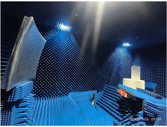
Figure 21 Compact-Range RCS and Antenna Test System
Where to Buy:
🔵 Antenna Test Systems are now available to order from SEA Components GmbH, the official Ceyear partner in the European Union. For sales inquiries and quotations, please contact us at tm@sea-ceyear.com